For the whole story, click here. For the previous part of the story, click here. For the next part of the story, click here.
A "Sparkey" friend of mine joined with me on this project. He has it in mind to return to the electrification of VWs business. He has done this twice in the past, first in the mid to late 1970s and again in the late '80s, each time ramping up as the economics and consumer interest waxed, and discontinuing the effort as economics and consumer interest turned disfavorable. He says the time is right once more for a resurgence in electrification, so he and I entered into this venture together; he has the experience and know-how, and I have the machine shop capabilities and paying customer. (Or, at least I had a paying customer when we started the project!)
So, we worked out our plan. One key aspect was the electric motor. Because we're making our own controller, we'd like to have the benefits of a series wound motor (great acceleration) and a shunt-wound motor (great regeneration). We opted for a 10 battery system and ordered a custom, carefully selected set of 10 "traction" lead-acid batteries. They're designed for this service. Our design goals are outlined here.
I chose the placement for the batteries and went for five as nearly exactly on top of the rear wheels as possible and five above the front axle as nearly as possible too. This makes for two "half-packs" which also permits some optimizations on control as well. The design calls for half-pack voltage meter, whole-pack voltage meter, accessory battery (for non-propulsion circuits) voltage meter, and an ammeter to show the real-time consumption of electric power by the motor.
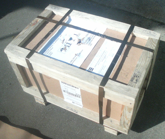
As per our plan, we designed and ordered up a custom-designed dual-winding motor from Eastern Europe and about 8 months later, I received this:
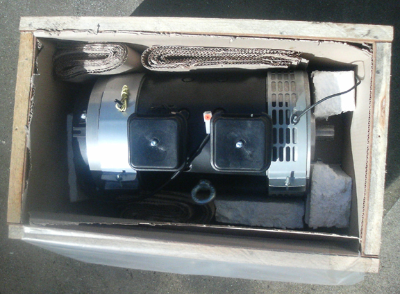
And removed from the crate, I got this:
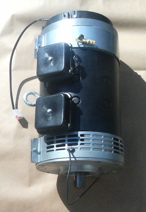
The two plastic boxes on the side are where the two sets of windings get attached.
It's an awesome motor, with built-in tachometer sending unit, built-in temperature probe, and they even added an accessory fan for free! (It turns out the accessory fan makes the assembly too long, so we'll use it elsewhere.) The motor sports dual-brushes, too. And, as for acceleration and power, it's got a very tall RPM range and produces power from dead-stopped to 4000 RPM, so while similar to a VW engine (stock service limit 4300 RPM), it's actually far more capable because it supplies more torque than the VW engine over the whole RPM range whereas a gasoline powered engine produces torque and power on a fairly "peaky" RPM curve. So, we're confidant that it'll easily out-run its gasoline counterpart. And, also importantly, we're confidant that the stock transaxle gearing will be suitable for our purposes.
One thing that got "lost in translation" was the strategy of attachment of the VW flywheel to the motor arbor, so I needed a hub to mate a flywheel to the motor, and, due to length, I couldn't use a standard off-the-shelf part from a Volkswagen EV kit. (Same thing for the mounting of the motor to the transaxle, too, by the way!)
So, I got on the lathe, made a round piece with a shoulder for the flywheel that would index on the OD, mated to the maximum length of the motor shaft, broached a keyway, slit it, made threaded high-grade pinch bolt bores, drilled dowel pin holes and threaded four high-grade mounting bolts for the flywheel to the hub. I finished all this off by balancing the flywheel on the hub, with the pressure plate, and then made a special bushing for the transaxle input shaft.
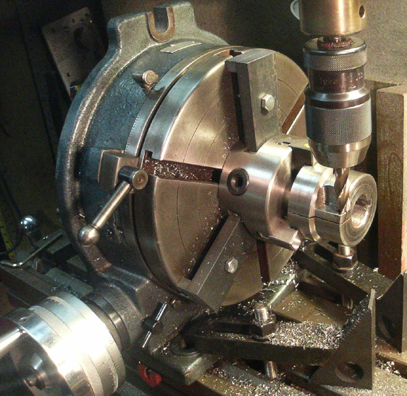
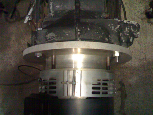
I photographed some of this. The following image shows the hub nearly completed - I was just facing off the area for the pinch bolt bores - I used M8 X 1.25 socket head screws in grade 10.2.
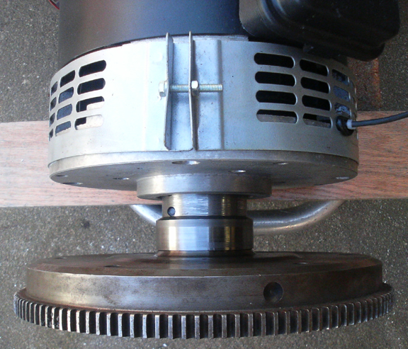
As you can see in the image below, access to the inner pinch bolt's heads is restricted by the motor's mounting flange's centering feature. So, to provide access to the hub's inner pinch bolt, I had to machine a slot into said centering flange (not visible below). Here below, the flywheel is mounted to the motor via the hub:
As mentioned above, I had to fabricate a bushing for the input shaft to ride in, which is ordinarily done by the "gland nut" that attaches the flywheel to an engine. I took some images of it installed, but the lighting was poor and they didn't turn out, but the time I realized it, the assembly was already bolted up!
Next, I had to fabricate the motor to transaxle mounting plate. This I did in two aluminum parts bolted on and together with four high-grade socket head screws. Making the plate was hard because of the size and the need for holding pretty good tolerances for concentricity across several parts.
This was a lot more tricky than it might appear, but I don't want to give away the ingredients to all my secret sauces! So, these few images will have to suffice - lets just say, this is not a trivial job...
First, the mounting plate:
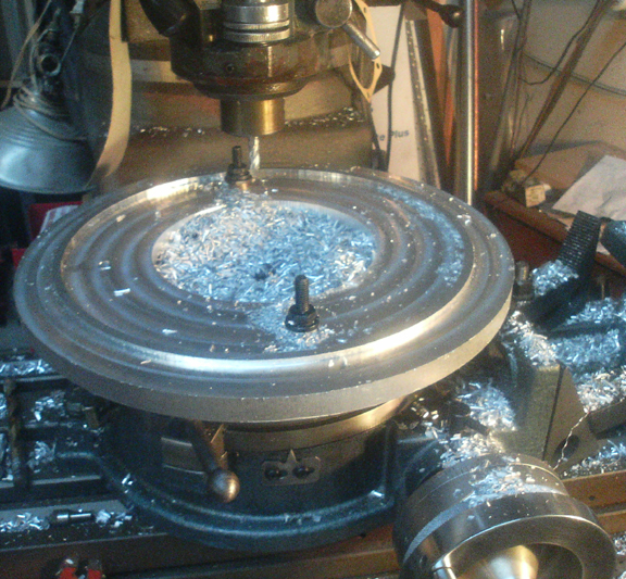
Note the motor mounting holes are already bored, now the flange that centers the motor on the transaxle has to be cut - it's an "out-facing" ring that has to fit the outer rim of the transaxle. The overall tolerance is not published by VW, but the input shaft must center on the motor to within a few thousandths of an inch to prevent energy loss and undue wear at the transaxle's input shaft.
![]()
Cutting the center away was a lot more challenging than it might appear here...
OK, the plate's all done except the mounting holes to the transaxle (no photos of that), but then there's the "spacer", that centers and spaces everything.
The spacer has the same basic problem - how to cut the center out when you have to cut the the part's OD, which happens to be right at the limit of - and perhaps too large for- the lathe?! AND keep it to half a thousandth tolerance!
![]()
I know, it looks really easy... but it's not, especially if you don't want to turn all the unneeded material into chips. (Hint: Any time a part is removed from a lathe or mill, it is non-trivial to return it to the machine tool accurately alligned to where it had been before.)
OK, OK, here's a little more about doing the spacer - look carefully, the spacer is on the left!
![]()
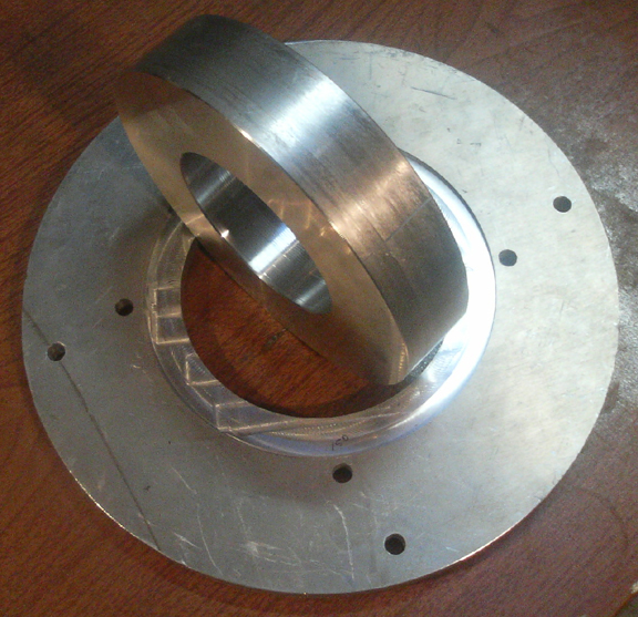
Here are the completed parts, the outer, larger radius holes are for the transaxle, and inner ones allow attachment of the mounting plate to the electric motor. The mounting plate's motor side is shown here - the centering ring (or simply "spacer") fits into the recess. The critical dimensions are:
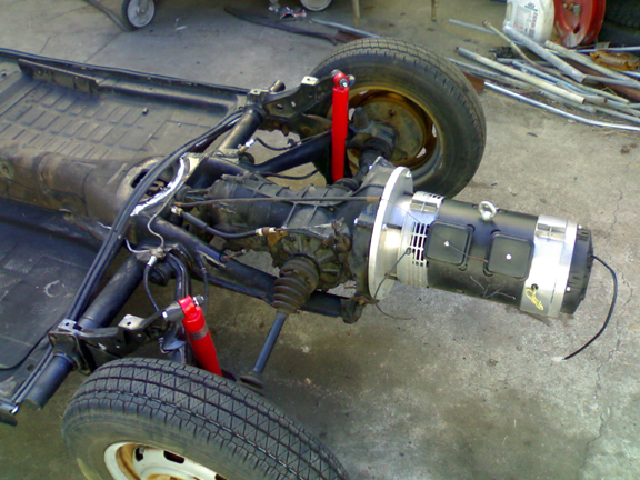
And here they are all installed:
Yet to be added: Images of the batteries, controller, and charging system.
Want to see more of this vehicle?
For the whole story, click here. For the previous part of the story, click here. For the next part of the story, click here.